ECE5725 Final Project
Nixie Clock
A Project By Tianyu Liang and Guangyuan Li.
Demonstration Video
Introduction
For this project, we designed all the circuits and the software by ourselves. For the power supply, we have to use two different power supplies. One is about 170V for the nixie tube, the other is 5V for the RPi. Theoretically, we can get 120*1.414=170V from standard voltage. So we will use a full bridge rectifier and a smooth circuit to get a 170VDC. For the 5V power, we will use an external power or a transformer (depends on the budget). Next problem is the control of the clock. To control the six nixie tubes, we need to control 6*10=60 pins using the RPi. To achieve this, we used at least eight 74HC595,the 8-bit parallel-out shift register. Also used transistors that can tolerate high voltages as switches to control the tubes and also use them to do the insulation work. We also want to add some back lights at the bottom of the tubes to make the clock look more fancy or use the lights to realize other functions. For the software part, we need to generate waveforms to drive the shift registers to control the number shown in the tubes. Also we need to make an interface that can let us change time and do other things.
Project Objective:
- A nixie clock with multiple backlights controlled by Raspberry Pi.
- Manual input or load local time as current time.
- Alarm clock function, one alarm time stored.
- Stopwatch function.
Design
Hardware
Driver
Each Nixie tube requires 10 control pins and LED backlights require 4 control pins, which means we need 64 total control pins,
which is outnumber the available GPIO pins provided by one RPi. We used 8 TI 74HC595 shift registers to solve this problem,
and the package of one shift register is shown in Figure 1. U1 represents the first shift register unit and Pn_m represents the control signal
to tube n pin m.
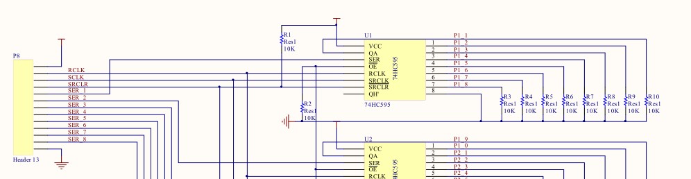
Figure 1. Package of the 74HC595
The function of the shift register here is to take in serial data from RPi and decode it to parallel data, which is used to control the tubes and the backlight.
The pins that need to be controlled by RPI are SER, RCLK, SRCLK and SRCLR, where RCLK, SRCLK and SRCLR are shared by all shift registers and each SER is controlled by one GPIO pin.
SER pin is the serial data input and QA to QH are parallel outputs.
SRCLK is the clock of the serial data. RCLK is used to control the output register. When there is a positive edge on the RCLK,
the output register will pop the converted data in the buffer to the output. SRCLR is used to clear the data we input to the buffer.
It is triggered when low. So we have to pull up this pin using a 10k resistor as shown in Figure 1.
The Output Enable pin is pulled down using a 10k resistor to make sure the output of the shift register will alway be enabled.
For the parallel data output pins, we also pulled down using 10k resistors to make sure the output is a logic zero when there is no signal output.
The correctness and functionality of shift register was simulated using FPGA before the PCB was sent for manufacturing, and the simulation timeline is
shown in Figure 2.
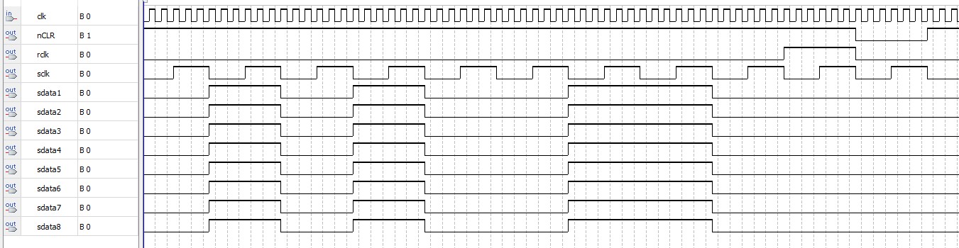
Figure 2. Simulation timeline of the 74HC595 package
We used FPGA to do the timeline test because it is much easier to program this in verilog. As shown in Figure 2,
the SRCLK(sclk) is always ticking. When the 8-bit data is transferred(we transferred 10100110), we pulled up the RCLK(rclk).
After a clock cycle, we pulled down the RCLK(rclk) and pulled down SRCLR(nCLR) to clear all the data in the buffer. After another clock cycle,
we pulled up SRCLR(nCLR) and one transfer is completed.
Tube Board
The nixie tube we used for our clock is IN2, and the schematic of the nixie tubes is shown in Figure 3
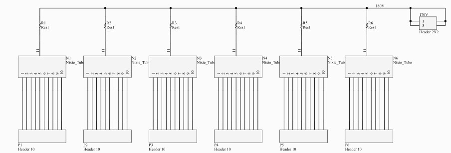
Figure 3. Schematic of nixie tube board wiring
Each nixie tube has 11 pins, and 10 among them are cathode which light up each plate represeting the number in the tube, while
the remaind one is a cathode that finishe the circuit.
The anode of the nixie tube is connected to 170V through a resistor. The reason why we put a resistor here is that we can measure
the voltage drop between the resistor to get the current. So the value we used for the resistor is 1Ω. The cathode of the tubes are
connected to a header which will finally connect to the collector of a BJTs on the driver board.
Transistor Wiring
We used BJTs to let the output pins of shift registers to drive nixie tubes. The only important spec when choosing BJTs here is
that it should tolerate high collector voltage, so we chose MPSA42. Its collector-base voltage is 300V which is perfect for the nixie
tube clock we built, and the schematic of BJT wiring is shown in Figure 4. We have six blocks in our circuit for the 60 cathode pins of the six tubes.
Since there are 4 pins left, we used the remaining 4 pins to control the back lights of the clock.
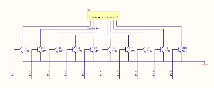
Figure 4. Schematic of BJT connecting to tube pins
LED Wiring
The LEDs we used are dual color SMD LEDs, six BLUE-GREEN LEDs and six RED-YELLOW LEDs in total. We put one LED each under each nixie tube so that we will have four different colors and can combine these
four colors to make new colors. Each LED is driven by two BJTs. To make layout less difficult, we used one BJT to drive three LEDs, so there are eight
BJTs in the driving circuit of LEDs.
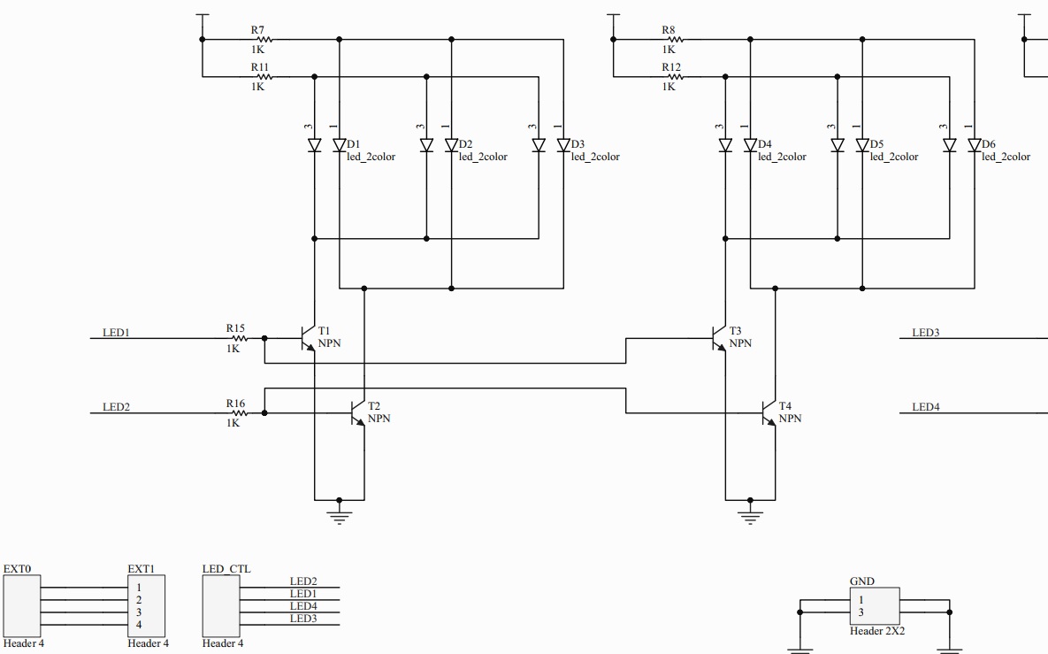
Figure 5. Schematic of LED control signal
As shown in Figure 5, one LED control signal connects to six pins in six dual-color LEDs. A dual-color LED has two control pins and each color is controlled by one
pin. This means that we have four control signals, each controls one kind of back lights in all six nixie tubes.
We also added a header between the output of the shift register and the LED driving circuit.
The reason we did that is if we don’t want to use shift registers to control the LEDs for example making the leds breathing,
we can disconnect the headers and connect the control pin to other signal sources.
Power
We directly draw voltage from the wall and use a full bridge rectifier and smoothing circuit to convert AC to DC. The circuit is shown in Figure 6.
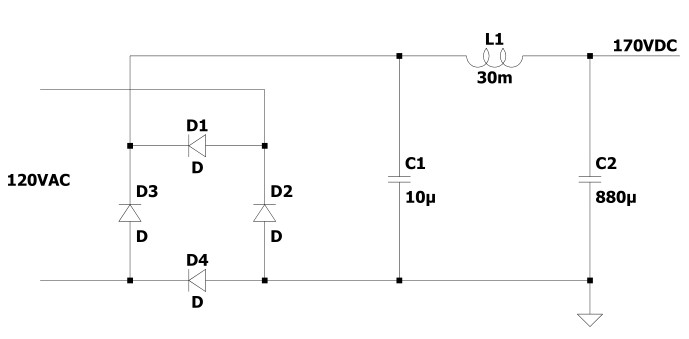
Figure 6. Schematic of LED control signal
Safety
Since we are dealing with high voltages, safety is very important. A fuse at the hot wire is necessary.
Also we put all the circuits into a metal closure, which is connected to the earth and also wrapped by duct tape.
Then we put the whole system into a plastic box to make a double insulation. After we finished the project,
we realized that we needed to use a transformer at the power supply to insulate the whole circuit and the wall.
Besides a transformer has intrinsic impedance, when there is a short circuit, it will limit the current to some extent.
However, the capacitors will still have charge in them when the power is off, so the discharging of capacitors are also necessary.
Since the impedance of the anode of the nixie tubes are very high, we parallel the whole system with two 51k resistors.
The reason why we use two 51k resistors instead of one 100k is that we only have the 0.25w resistors.
It is always important to calculate the power when choosing resistors for circuits using high voltages.
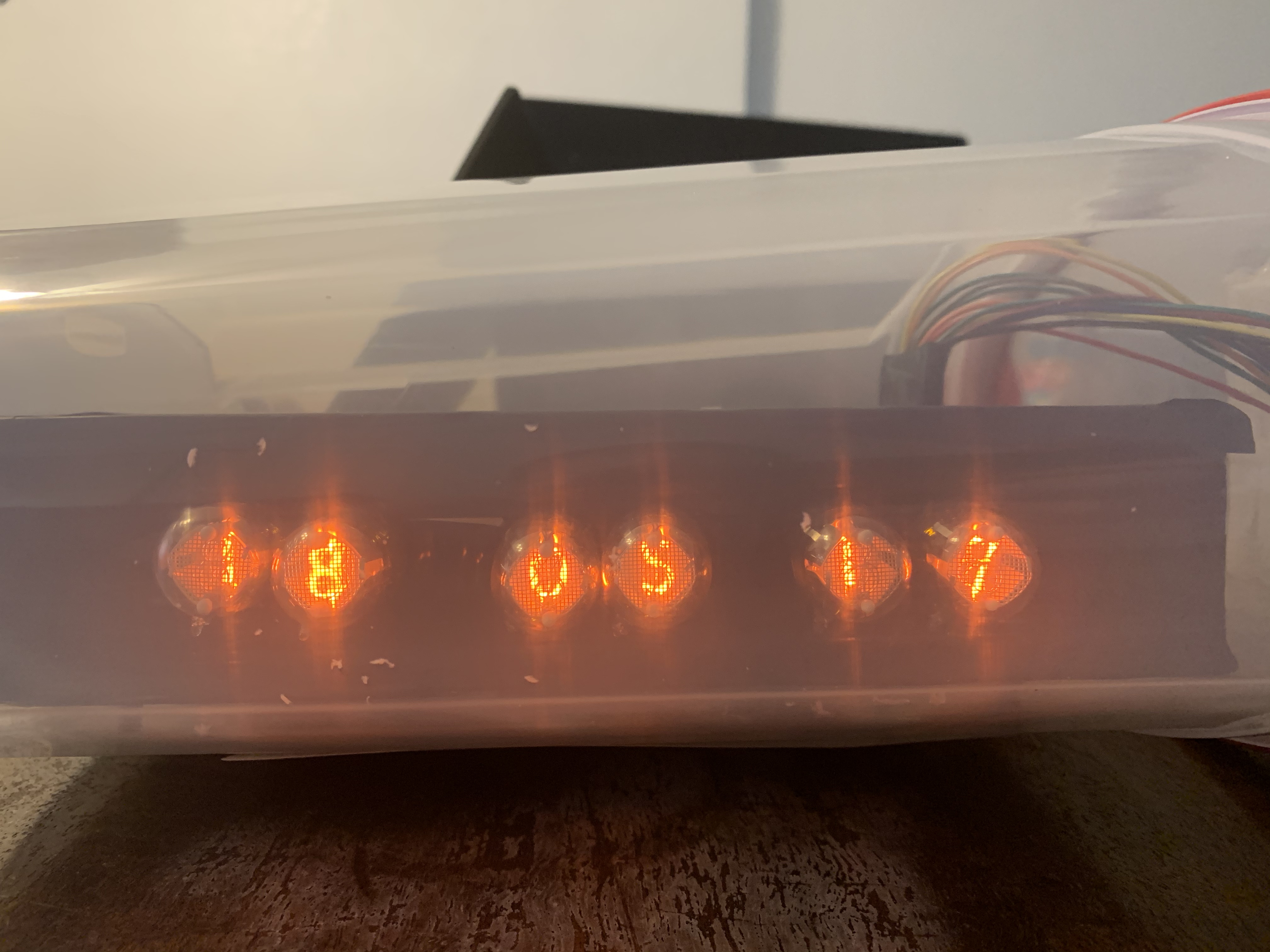
Figure 7. Front look on the Nixie clock
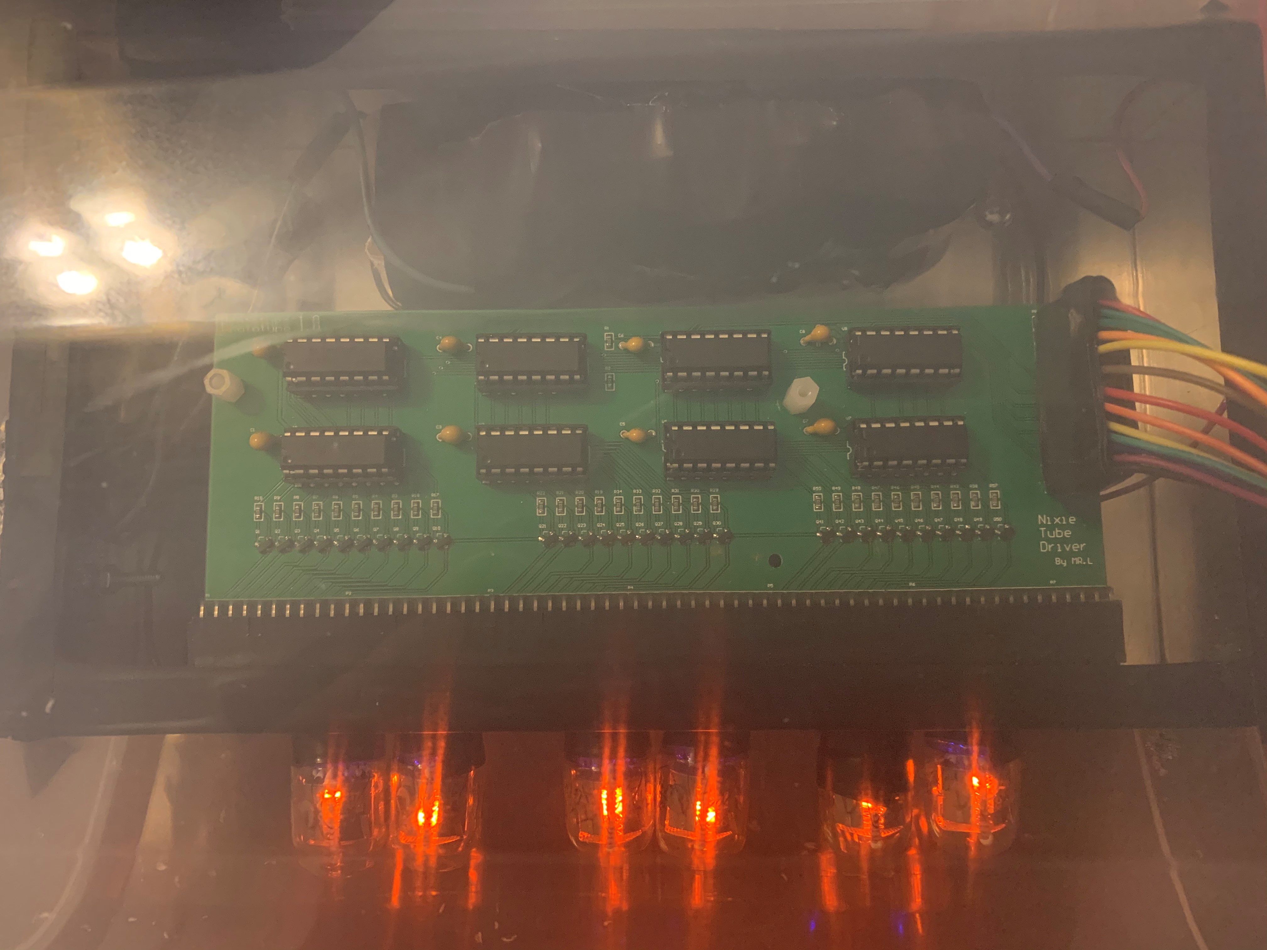
Figure 8. Top look on the Nixie clock
Figure 7 and 8 each shows the front and top vision of our nixie clock, it can be noticed that the PCB connects to each part of the clock locates in a box which is wrapped with duct tape, and the box is double insulated in a plastic container, which has an open hole allowing cable connection from the Rpi.
Software
Driver Loading Function
There are several goals that we need to accomplish in the driver program. The first one is to program the timeline that we can output
data to the shift registers. The code is shown in write_register function in the Code Appendix.
We also pull up and pull down the GPIO pins according to the timeline shown in Figure 2.
The second thing we need to do in the driver program is that we need to map the pins. For example,
we need to write a program to map what we want the nixie tubes to show to what data we should write to the registers.
The functions are shown in load_to_serial_buffer function. And there is an array called data[] which contains all the data that we need to transfer
for each number we want tubes to show.
User Interface
For the user interface, we used the pygame library and the piTFT. We used event.get to detect each movement we made to
the touch screen. There are six different interfaces in total: the main page, set current time page, set alarm clock page,
stopwatch control page, number input page and LED manual control page. Each page is shown from Figure 9 to 14.
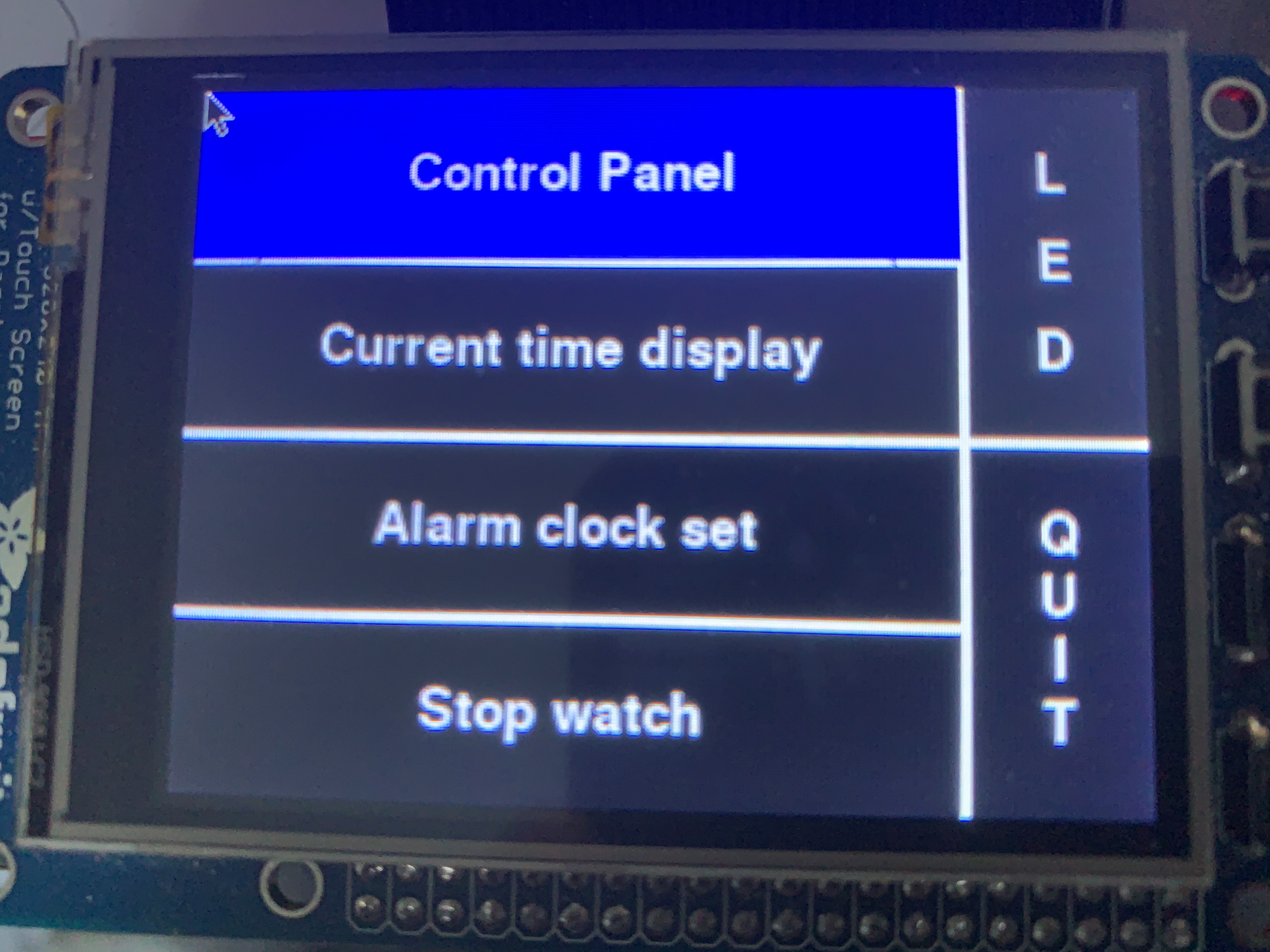
Figure 9. Main Page Interface
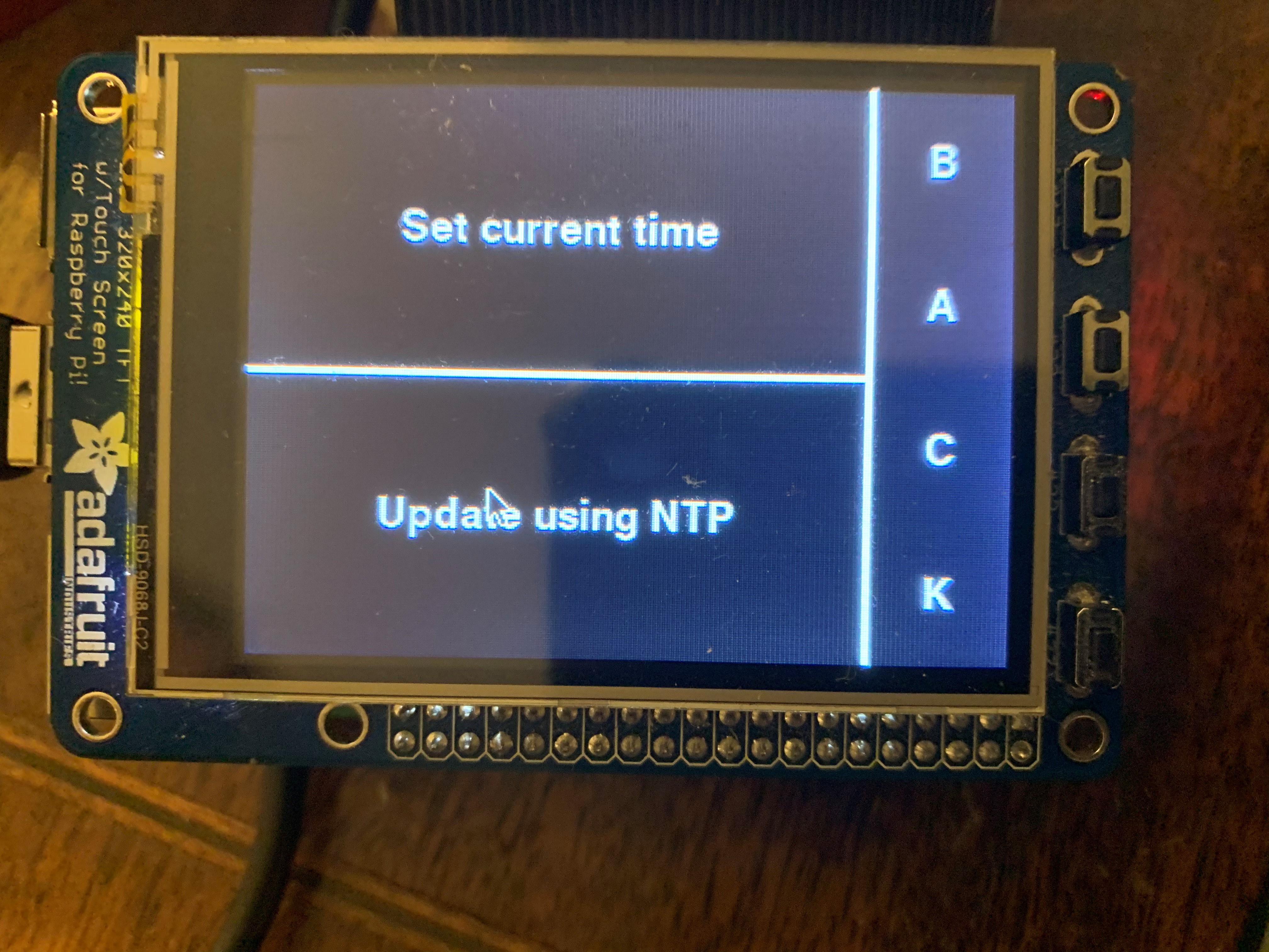
Figure 10. Set Current Time Page Interface
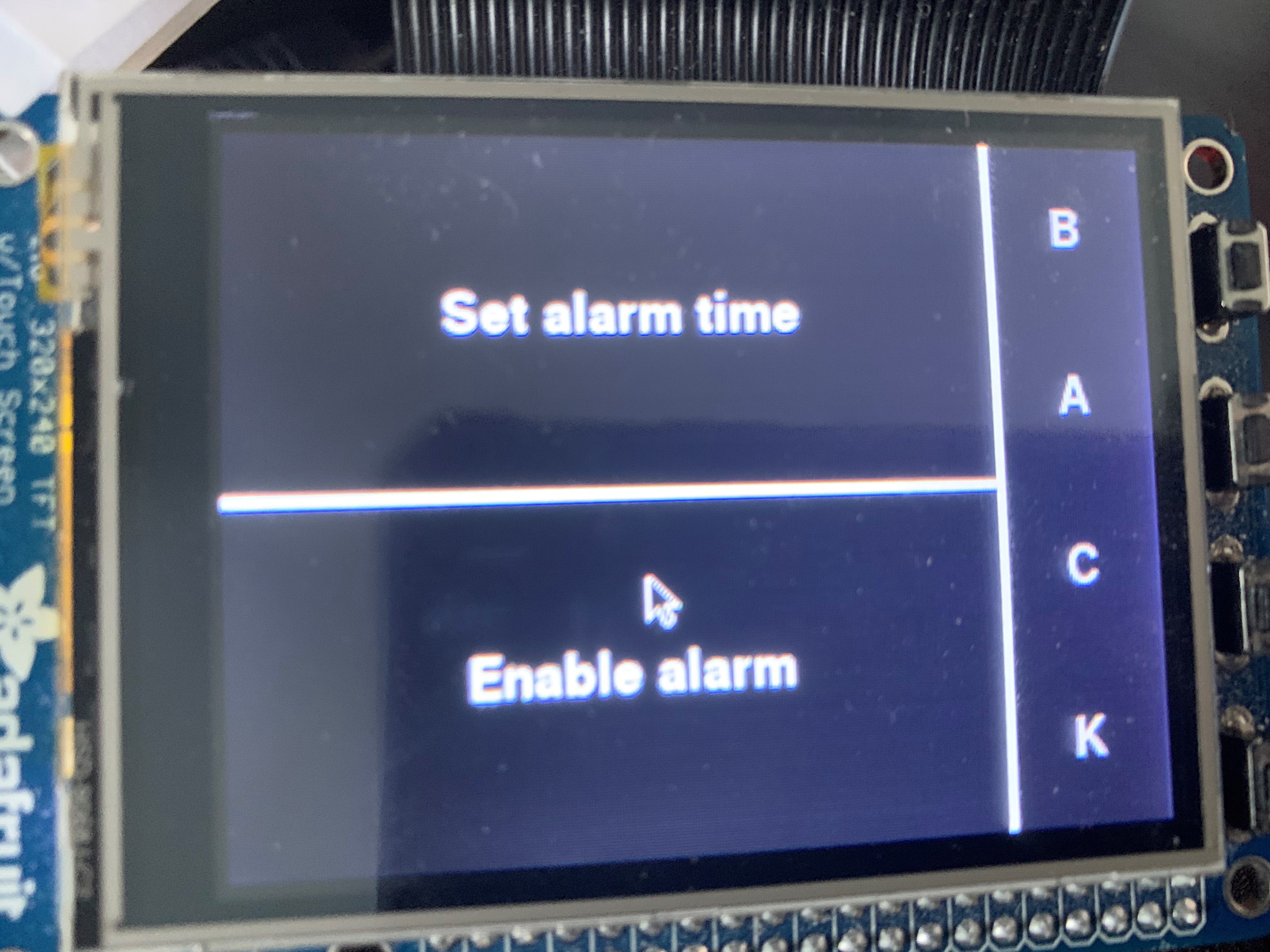
Figure 11. Set Alarm Clock Page Interface
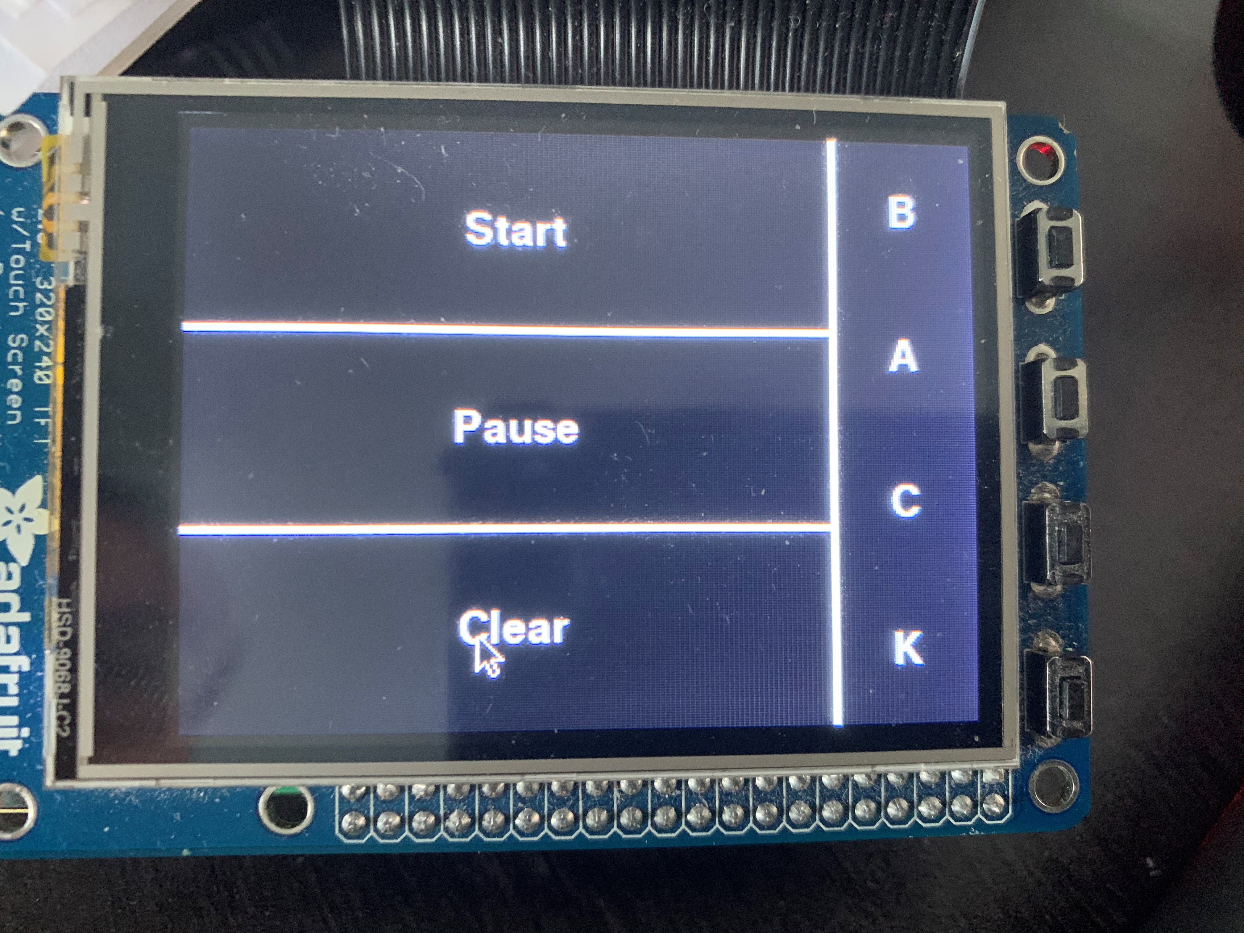
Figure 12. Stopwatch Control Page Interface
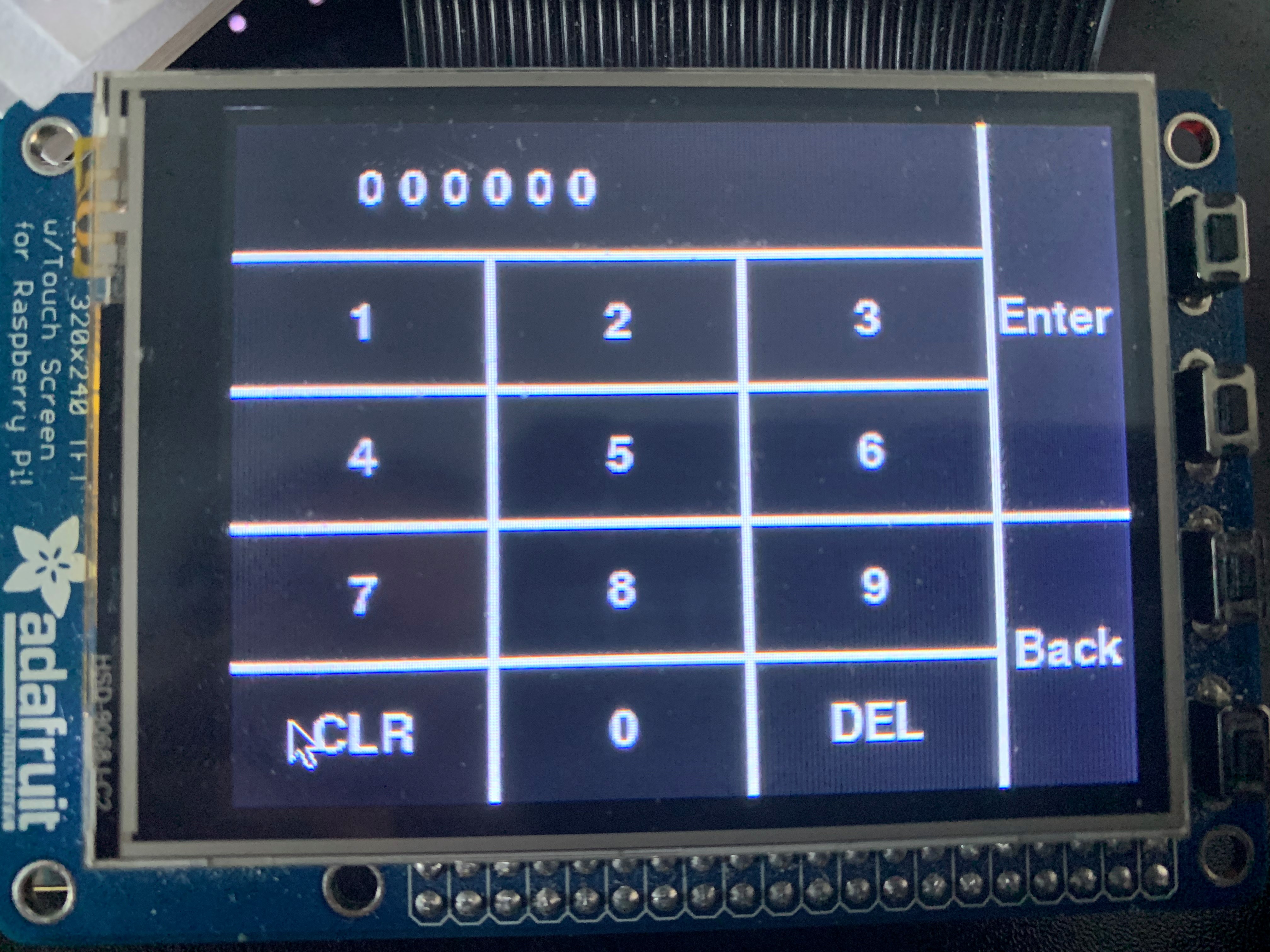
Figure 13. Time Input Page Interface
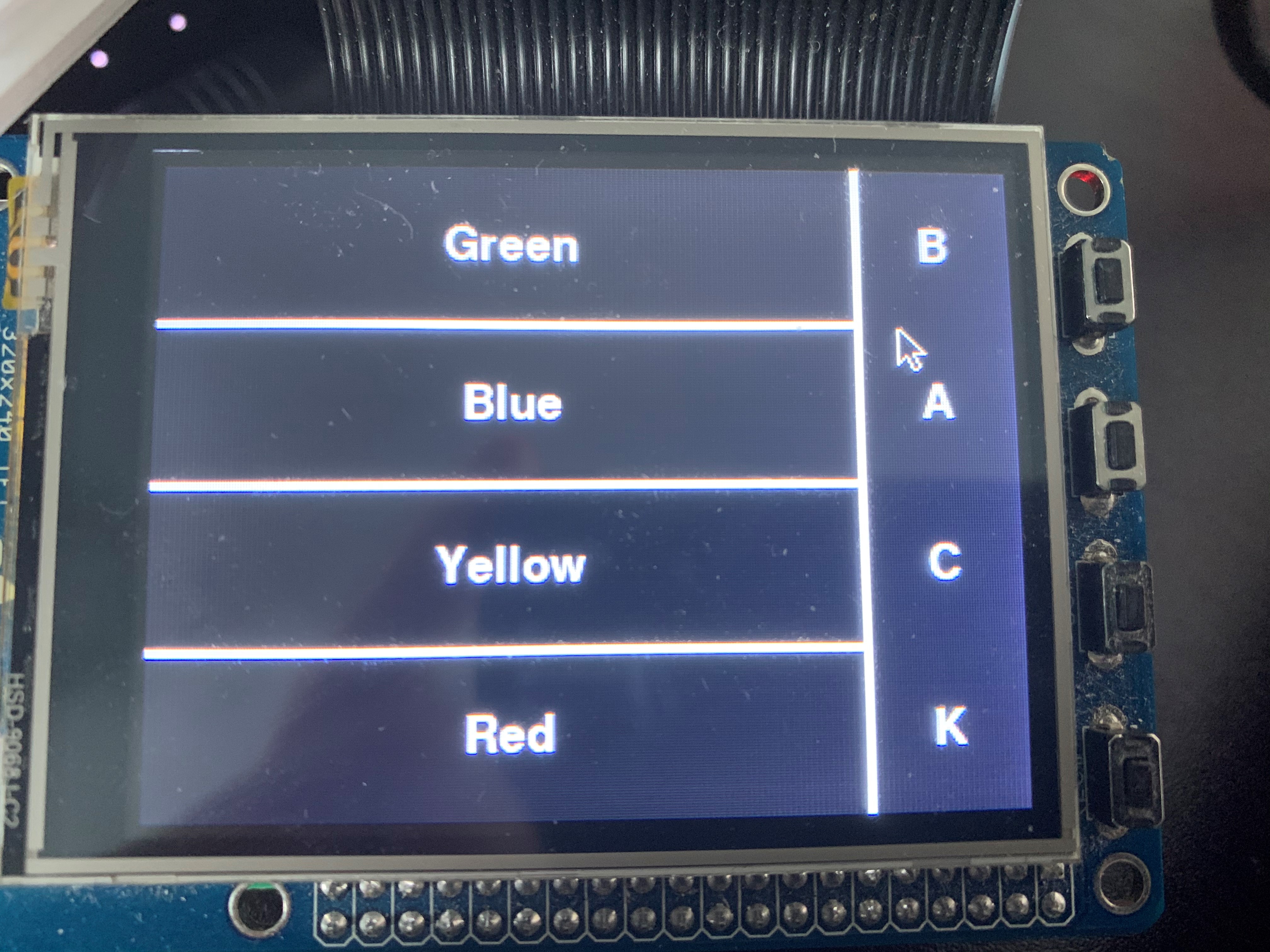
Figure 14. Backlight Control Interface
The main page allow user to navigate between different control interfaces. The set current time interface allow user to manually set current time
or automatically adjust time to local time on RPi, and the manual option will redirect to time input interface which allow user to input time and
change the display on the tubes. The alarm clock page will also allow user to manual input the one alarm clock time that will be stored locally and
an option to enable/disable the alarm. If the alarm is enabled, the "Enable alarm" pushbutton will light up as an indication, and back to normal if
disabled. In the stopwatch control panel, it allow user to start the stopwatch, pause it, resume and clear, which is the standard functionality of a
normal stopwatch. The backlight panel allow user to manually set the backlight on the tube to either one of the four color.
Functions
All functions we used in this project are attached in the Code Appendix.
Set Current Time Function
We defined an array in the program that contains the information of time(hour, minute, second), which increaments by 1 after each second.
We outputed numbers according to the numbers stored in the array. So if we want to change the time displaying, we just need to change the value
of the array. We programmed two ways for setting current time.
The first way is setting current time manually, which redirects to the time input page control panel, which stores the time inputed in the array
corresponding to the user interaction on PiTFT. The other way is to update the time according to the local time of RPi. We wrote a function to read the
local time from RPi using python datetime library and output the time to the array.
Set Alarm Function
We defined another array to store one alarm time. The alarm time is manually inputted using the similar method as we did in the set current time method.
Also we defined a parameter to check the current time with the alarm from time to time, if the time matches, the backlights on the tubes will flash as
the alarm. We also allow user to maunally set the alarm on or off, it the alarm clock is disabled, it will not alarm but the presetted time is still stored.
Stopwatch Function
The stopwatch function will clear the tube numbers when it is called and we have the last two tubes represent represent tens of milliseconds instead of seconds
for the stopwatch. Also the middle two tubes represent seconds and first two tubes represents minutes now. When the start pushbutton of stopwatch control panel is
pressed, the tube numbers will start to increament and paused when the pause pushbutton is pressed. Then we can resume the counting by pressing the start again.
If clear is pressed at any time, the tube numbers will be cleared and keep couting or paused depends on the previous state.
Drawing
The overall schematic of both shift registers wiring and tube board wiring is shown below
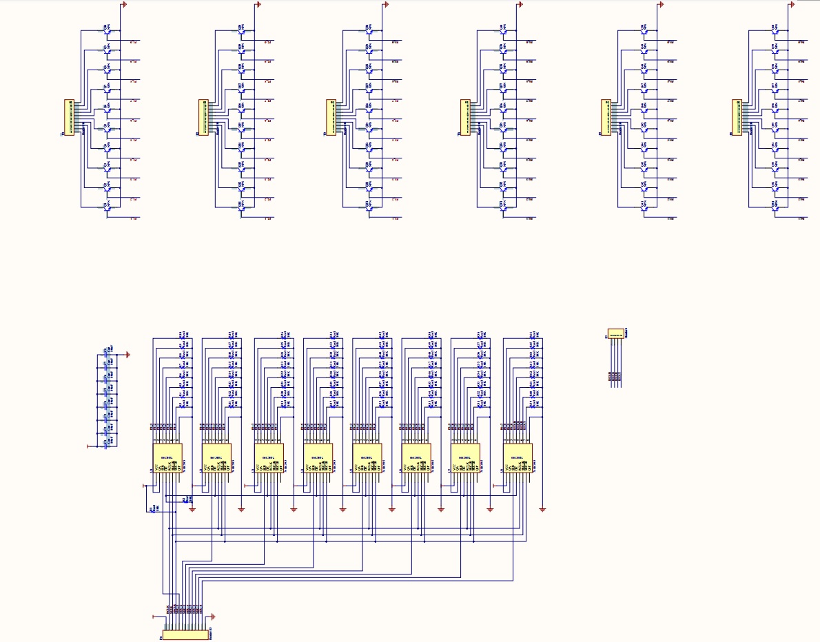
Figure 15. Shift register wiring
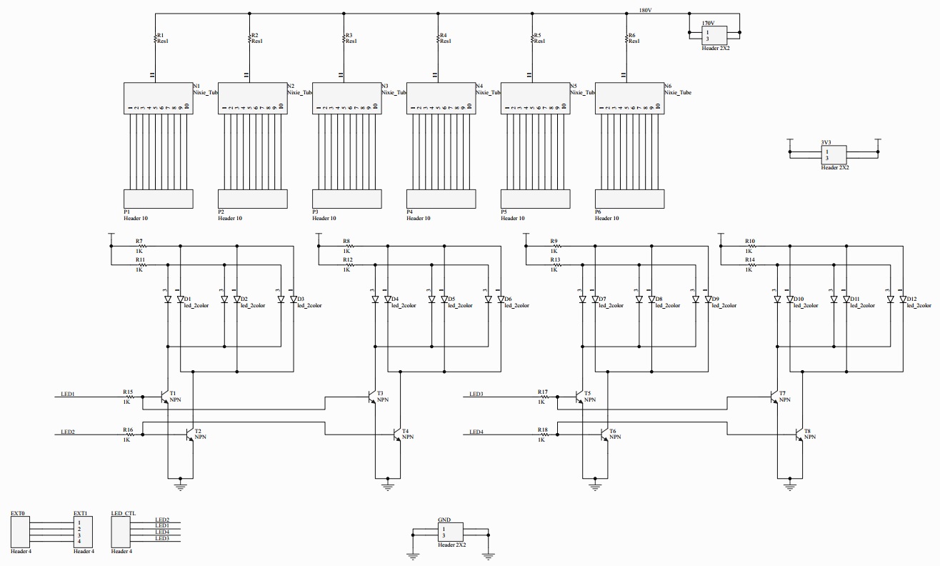
Figure 16. Tube board wiring
Testing
The tests of our hardware system have been first simulated using FPGA before we build the PCB. Due the the complexity of the hardware wiring, it is
unlikely to build it on the protoboard, so we choose the PCB fabrication, and the final PCB board met exactly as our simualtion result.
The software tests of this project were perfomed on Raspberry Pi. We started by writing each function alone on seperate python file and have them
functionality verified before combining to the main code file. Then we performed main code simulatiion on the nixie clock and have everything verified
before the demonstration of this project.
Result
The nixie tubes and the back lights work exactly as planned, and the functionality of our final code meet our expectation as well. This means that the overall design meets our plan. However, due to the lack of experience on projects with such high voltage, we made several small mistakes during the building and these will be solved in the future work. Overall, despite there are still some flaws in the final product, it is still an interesting clock that can be placed for decoration and it is a pleasing experience to build this clock.
Future Work
There are several small mistakes that need to be modified. For the circuit with BJTs, we forgot to put a resistor at the base to limit the current.
Without this resistor, the shift register will not function well in extreme conditions such as the outputs are all 1. Besides, we misdrew the
package of the BJT, so we need to correct it in the future. We also need to use a transformer in the power supply because rectifying the voltage
directly is very dangerous.
One thing that we need to add in the future is that we will build a boost circuit so that we can just use a usb port to power the clock and it is
much safer. Since RPi is powerful, we can explore what other functions can be realized on the six nixie tubes.
Work Distribution

Tianyu Liang
tl783@cornell.edu
Designed the overall hardware architecture and hardware drive.

Guangyuan Li
gl499@cornell.edu
Designed the software functions and tested the overall system.
Parts List
| Component | Quantity | Price |
|---|---|---|
| Resistor 1K(SMD) | 12 | 0.00924 |
| Resistor 10K(SMD) | 66 | 0.5082 |
| Capacitor 0.1uF | 8 | 0.08 |
| Capacitor 10uF | 1 | 1 |
| Capacitor 220uF | 4 | 5 |
| Inductor 30mH | 1 | from the lab |
| MPSA42 transistor(SMD) | 68 | 12 |
| 74HC595 | 8 | 2.24 |
| IN-2 nixie tube | 6 | 25 |
| Blue-green LED | 6 | 3.636 |
| Red-yellow LED | 6 | 2.316 |
| PCB(printed by JLC PCB) | 2 | 10 |
| Metal closure | 1 | 12 |
| Plastic case | 1 | 10 |
| Fuse | 1 | 0.6 |
| Wires and connectors | N/A | from the lab |
| Raspberry Pi 3 model B | 1 | from the lab |
| piTFT | 1 | from the lab |
| Total | 84.38944 |
References
74HC595 8-bit Shift Register DatasheetIN-2 Nixie Tube Datasheet
MPSA42-D BTJ Datasheet
BLUE-GREEN LED Datasheet
RED-YELLOW LED Datasheet
R-Pi GPIO Document
Code Appendix
data.py, which contains data that we use for corresponding shift register value to tube number
#ab
#a--which tube
#b--what number

data_table = (
        0B00000001,     #00
        0B00000010,     #09
        0B00000100,     #08
        0B00001000,     #07
        0B00010000,     #06
        0B00100000,     #05
        0B01000000,     #04
        0B10000000,     #03
        0B00000001,     #02
        0B00000010,     #01
        0B00000100,     #10
        0B00001000,     #19
        0B00010000,     #18
        0B00100000,     #17
        0B01000000,     #16
        0B10000000,     #15
        0B00000001,     #14
        0B00000010,     #13
        0B00000100,     #12
        0B00001000,     #11
        0B00010000,     #20
        0B00100000,     #29
        0B01000000,     #28
        0B10000000,     #27
        0B00000001,     #26
        0B00000010,     #25
        0B00000100,     #24
        0B00001000,     #23
        0B00010000,     #22
        0B00100000,     #21
        0B01000000,     #30
        0B10000000,     #39
        0B00000001,     #38
        0B00000010,     #37
        0B00000100,     #36
        0B00001000,     #35
        0B00010000,     #34
        0B00100000,     #33
        0B01000000,     #32
        0B10000000,     #31
        0B00000001,     #40
        0B00000010,     #49
        0B00000100,     #48
        0B00001000,     #47
        0B00010000,     #46
        0B00100000,     #45
        0B01000000,     #44
        0B10000000,     #43
        0B00000001,     #42
        0B00000010,     #41
        0B00000100,     #50
        0B00001000,     #59
        0B00010000,     #58
        0B00100000,     #57
        0B01000000,     #56
        0B10000000,     #55
        0B00000001,     #54
        0B00000010,     #53
        0B00000100,     #52
        0B00001000,     #51
        )


#which GPIO pin to use for serial 1 to 8
port_table = (
        19,             #serial 1
        26,             #serial 2
        21,             #serial 3
        20,             #serial 4
        16,             #serial 5
        12,             #serial 6
        24,             #serial 7
        4               #serial 8
        )
main.py, main code that includes all function we used in our project
# Include libraries import RPi.GPIO as GPIO import data import time import os import pygame from pygame.locals import * from datetime import datetime #############--TFT settings--################ os.putenv('SDL_VIDEODRIVER', 'fbcon') os.putenv('SDL_FBDEV', '/dev/fb1') os.putenv('SDL_MOUSEDRV', 'TSLIB') os.putenv('SDL_MOUSEDEV', '/dev/input/touchscreen') pygame.init() #pygame.mouse.set_visible(False) WHITE = 255,255,255 RED = 255,0,0 GREEN = 0,255,0 BLUE = 0,0,255 BLACK = 0,0,0 screen = pygame.display.set_mode((320,240)) loop_run = 1 #user location: 0 front page # 1 current time display # 11 set current time # 2 alarm clock set # 21 set alarm clock time # 3 stop watch ########################################## ##########--Variable Initialize--######### ########################################## user_location = 0 input_cursor = 0 current_time_array = [0,0,0,0,0,0] alarm_time_array = [0,0,0,0,0,0] #alarm clock alarm_second = 0 alarm_minute = 0 alarm_hour = 0 alarm_enable = False alarm_flag = False #if arrive at the time true, set false when set alarm_enable false #stop watch stop_watch_en = False stop_watch_run = False stop_watch_clr = False # Function return local time def get_current_time(): t = datetime.now().time() # change time from string to a list of int [hour, minute,second] cur_time = list(map(int, t.strftime("%H:%M:%S").split(":"))) return cur_time ########################################## #########--user interface functions--##### ########################################## def display_screen(user_location): screen.fill(BLACK) display_draw_interface(user_location) pygame.display.flip() def display_my_buttons(my_buttons): for my_text, text_pos in my_buttons.items(): text_surface = my_font.render(my_text, True, WHITE) rect = text_surface.get_rect(center=text_pos) screen.blit(text_surface, rect) def display_draw_interface(user_location): if(user_location == 0): pygame.draw.line(screen, WHITE, [0,60], [260,60], 3) pygame.draw.line(screen, WHITE, [0,120], [320,120], 3) pygame.draw.line(screen, WHITE, [0,180], [260,180], 3) pygame.draw.line(screen, WHITE, [260,0], [260,240], 3) pygame.draw.rect(screen, BLUE, [0,0,260,60]) display_my_buttons(frontpage_buttons) elif(user_location == 1): pygame.draw.line(screen, WHITE, [0,120], [260,120], 3) pygame.draw.line(screen, WHITE, [260,0], [260,240], 3) display_my_buttons(current_time_buttons) elif(user_location == 11): pygame.draw.line(screen, WHITE, [0,48], [270,48], 3) pygame.draw.line(screen, WHITE, [0,96], [270,96], 3) pygame.draw.line(screen, WHITE, [0,144], [320,144], 3) pygame.draw.line(screen, WHITE, [0,192], [270,192], 3) pygame.draw.line(screen, WHITE, [90,48], [90,240], 3) pygame.draw.line(screen, WHITE, [180,48], [180,240], 3) pygame.draw.line(screen, WHITE, [270,0], [270,240], 3) display_my_buttons(time_input_buttons) for i in range (6): text_surface = my_font.render(str(current_time_array[i]), True, WHITE) rect = text_surface.get_rect(center=(48+i*15,24)) screen.blit(text_surface, rect) elif(user_location == 2): pygame.draw.line(screen, WHITE, [0,120], [260,120], 3) pygame.draw.line(screen, WHITE, [260,0], [260,240], 3) if(alarm_enable): pygame.draw.rect(screen, GREEN, [0,120,260,240]) display_my_buttons(alarm_clock_buttons) elif(user_location == 21): pygame.draw.line(screen, WHITE, [0,48], [270,48], 3) pygame.draw.line(screen, WHITE, [0,96], [270,96], 3) pygame.draw.line(screen, WHITE, [0,144], [320,144], 3) pygame.draw.line(screen, WHITE, [0,192], [270,192], 3) pygame.draw.line(screen, WHITE, [90,48], [90,240], 3) pygame.draw.line(screen, WHITE, [180,48], [180,240], 3) pygame.draw.line(screen, WHITE, [270,0], [270,240], 3) display_my_buttons(time_input_buttons) for i in range (6): text_surface = my_font.render(str(alarm_time_array[i]), True, WHITE) rect = text_surface.get_rect(center=(48+i*15,24)) screen.blit(text_surface, rect) elif(user_location == 3): pygame.draw.line(screen, WHITE, [0,80], [260,80], 3) pygame.draw.line(screen, WHITE, [0,160], [260,160], 3) pygame.draw.line(screen, WHITE, [260,0], [260,240], 3) display_my_buttons(stop_watch_buttons) elif(user_location == 4): pygame.draw.line(screen, WHITE, [0,60], [260,60], 3) pygame.draw.line(screen, WHITE, [0,120], [260,120], 3) pygame.draw.line(screen, WHITE, [0,180], [260,180], 3) pygame.draw.line(screen, WHITE, [260,0], [260,240], 3) display_my_buttons(led_buttons) # Things that can be displayed my_font = pygame.font.Font(None, 25) frontpage_buttons = {"Control Panel": (130, 30), "Current time display": (130, 90), "Alarm clock set": (130, 150), "Stop watch": (130, 210), "L": (290, 30), "E": (290, 60), "D": (290, 90), "Q": (290, 150), "U": (290, 170), "I": (290, 190), "T": (290, 210)} current_time_buttons = {"Set current time": (130, 60), "Update using NTP": (130, 180), "B": (290, 30), "A": (290, 90), "C": (290, 150), "K": (290, 210)} alarm_clock_buttons = {"Set alarm time": (130, 60), "Enable alarm": (130, 180), "B": (290, 30), "A": (290, 90), "C": (290, 150), "K": (290, 210)} stop_watch_buttons = {"Start": (130, 40), "Pause": (130, 120), "Clear": (130, 200), "B": (290, 30), "A": (290, 90), "C": (290, 150), "K": (290, 210)} time_input_buttons = {"1": (45, 72), "2": (135, 72), "3": (225, 72), "4": (45, 120), "5": (135, 120), "6": (225, 120), "7": (45, 168), "8": (135, 168), "9": (225, 168), "CLR": (45,216), "0": (135, 216), "DEL": (225, 216), "Enter": (295, 72), "Back": (295, 192)} led_buttons = {"Green": (130, 30), "Blue": (130, 90), "Yellow": (130, 150), "Red": (130, 210), "B": (290, 30), "A": (290, 90), "C": (290, 150), "K": (290, 210)} # Initialize Screen display_screen(user_location) ############----Time Parameters----########## Tube = [0,0,0,0,0,0] Tube_number = [0,0,0,0,0,0] color = 64 serial_buffer = [0,0,0,0,0,0,0,2] second = 0 minute = 0 hour = 0 ###########----DRIVER Initialize----######### GPIO.setmode(GPIO.BCM) RCLK = 5 SCLK = 6 nCLR = 13 data1 = data.port_table[0] data2 = data.port_table[1] data3 = data.port_table[2] data4 = data.port_table[3] data5 = data.port_table[4] data6 = data.port_table[5] data7 = data.port_table[6] data8 = data.port_table[7] freq = 0.0001 GPIO.setup(RCLK, GPIO.OUT) GPIO.setup(SCLK, GPIO.OUT) GPIO.setup(nCLR, GPIO.OUT) GPIO.setup(data1, GPIO.OUT) GPIO.setup(data2, GPIO.OUT) GPIO.setup(data3, GPIO.OUT) GPIO.setup(data4, GPIO.OUT) GPIO.setup(data5, GPIO.OUT) GPIO.setup(data6, GPIO.OUT) GPIO.setup(data7, GPIO.OUT) GPIO.setup(data8, GPIO.OUT) #get temp number according to which tube abd which number def transfer_temp(tube_number): if(tube_number%10==0): temp_number = tube_number else: temp_number = (tube_number/10+1)*10-tube_number%10 return temp_number #using temp number to get which serial port to import data def get_serial(temp_number): serial_number = temp_number/8 + 1 return serial_number def load_to_serial_buffer(): for i in range(6): serial_num = get_serial(Tube_number[i]) - 1 serial_buffer[serial_num] = serial_buffer[serial_num] + data.data_table[Tube_number[i]] #write the shift register def write_register(): GPIO.output(RCLK, GPIO.LOW) GPIO.output(SCLK, GPIO.LOW) GPIO.output(nCLR, GPIO.HIGH) GPIO.output(data.port_table[0], GPIO.LOW) GPIO.output(data.port_table[1], GPIO.LOW) GPIO.output(data.port_table[2], GPIO.LOW) GPIO.output(data.port_table[3], GPIO.LOW) GPIO.output(data.port_table[4], GPIO.LOW) GPIO.output(data.port_table[5], GPIO.LOW) GPIO.output(data.port_table[6], GPIO.LOW) GPIO.output(data.port_table[7], GPIO.LOW) time.sleep(freq) for i in range(8): for j in range(8): temp = serial_buffer[j] << i temp = temp & 0B10000000 temp = temp >> 7 if(temp): GPIO.output(data.port_table[j], GPIO.HIGH) else: GPIO.output(data.port_table[j], GPIO.LOW) time.sleep(freq) GPIO.output(SCLK, GPIO.HIGH) time.sleep(freq) GPIO.output(SCLK, GPIO.LOW) for i in range(8): GPIO.output(data.port_table[i], GPIO.LOW) GPIO.output(RCLK, GPIO.HIGH) time.sleep(freq) GPIO.output(SCLK, GPIO.HIGH) time.sleep(freq) GPIO.output(RCLK, GPIO.LOW) GPIO.output(SCLK, GPIO.LOW) GPIO.output(nCLR, GPIO.LOW) time.sleep(freq) GPIO.output(SCLK, GPIO.HIGH) time.sleep(freq) GPIO.output(nCLR, GPIO.HIGH) GPIO.output(SCLK, GPIO.LOW) #put second minute hour into Tube array def Time_to_Tube(): Tube[0] = second % 10 Tube[1] = second / 10 Tube[2] = minute % 10 Tube[3] = minute / 10 Tube[4] = hour % 10 Tube[5] = hour / 10 def Tube_to_Tube_number(): for i in range(6): number_in = (5-i)*10+Tube[i] Tube_number[i] = transfer_temp(number_in) while loop_run: ############--clock function--#################### if(stop_watch_en): #second => 0.01sec minute => sec hour => minute time.sleep(0.008) if(stop_watch_run): second = second + 1 if(second == 100): second = 0 minute = minute + 1; if(minute == 60): minute = 0; hour = hour + 1; if(hour == 60): hour = 0; if(stop_watch_clr): second = 0 minute = 0 hour = 0 stop_watch_clr = False #default clock function else: time.sleep(1) second = second + 1 if(second == 60): second = 0 minute = minute + 1; if(minute == 60): minute = 0; hour = hour + 1; if(hour == 24): hour = 0; #if alarms led switches if(alarm_enable == True): if(second == alarm_second and minute == alarm_minute and hour == alarm_hour): alarm_flag = True if(alarm_flag): color = color * 2 if(color > 128): color = 16 Time_to_Tube() Tube_to_Tube_number() load_to_serial_buffer() write_register() serial_buffer = [0,0,0,0,0,0,0,color] ##################--user interface--################# for event in pygame.event.get(): if(event.type is MOUSEBUTTONUP): pos = pygame.mouse.get_pos() x,y = pos # front page if(user_location == 0): if(x < 260): if( 60 < y < 120): #current time display pressed user_location = 1 elif(120 < y < 180): #set alarm clock pressed user_location = 2 elif(180 < y < 240): #stop watch pressed stop_watch_en = True second = 0 minute = 0 hour = 0 user_location = 3 elif(260 < x < 320): if(y < 120): #LED pressed user_location = 4 elif(120 < y < 240): #quit pressed loop_run = 0 # set current time page elif(user_location == 1): if(x < 260): if( y < 120): #set current time pressed user_location = 11 elif(120 < y < 240): #NTP pressed hour, minute, second = get_current_time() elif(260 < x < 320): #back pressed user_location = 0 # enter time to set current time elif(user_location == 11): if(0 < x < 90): if( 48 < y < 96): #1 current_time_array[input_cursor] = 1 if(input_cursor == 5): input_cursor = 0 else: input_cursor = input_cursor + 1 elif(96 < y < 144): #4 current_time_array[input_cursor] = 4 if(input_cursor == 5): input_cursor = 0 else: input_cursor = input_cursor + 1 elif(144 < y < 192): #7 current_time_array[input_cursor] = 7 if(input_cursor == 5): input_cursor = 0 else: input_cursor = input_cursor + 1 elif(192 < y < 240): #clear current_time_array = [0,0,0,0,0,0] input_cursor = 0 elif(90 < x < 180): if( 48 < y < 96): #2 current_time_array[input_cursor] = 2 if(input_cursor == 5): input_cursor = 0 else: input_cursor = input_cursor + 1 elif(96 < y < 144): #5 current_time_array[input_cursor] = 5 if(input_cursor == 5): input_cursor = 0 else: input_cursor = input_cursor + 1 elif(144 < y < 192): #8 current_time_array[input_cursor] = 8 if(input_cursor == 5): input_cursor = 0 else: input_cursor = input_cursor + 1 elif(192 < y < 240): #0 current_time_array[input_cursor] = 0 if(input_cursor == 5): input_cursor = 0 else: input_cursor = input_cursor + 1 elif(180 < x < 270): if( 48 < y < 96): #3 current_time_array[input_cursor] = 3 if(input_cursor == 5): input_cursor = 0 else: input_cursor = input_cursor + 1 elif(96 < y < 144): #6 current_time_array[input_cursor] = 6 if(input_cursor == 5): input_cursor = 0 else: input_cursor = input_cursor + 1 elif(144 < y < 192): #9 current_time_array[input_cursor] = 9 if(input_cursor == 5): input_cursor = 0 else: input_cursor = input_cursor + 1 elif(192 < y < 240): #delete if(input_cursor == 0): input_cursor = 0 else: input_cursor = input_cursor - 1 current_time_array[input_cursor] = 0 elif(270 < x < 320): if( 0 < y < 144): #enter pressed input_cursor = 0 new_second = 10*current_time_array[4] + current_time_array[5] new_minute = 10*current_time_array[2] + current_time_array[3] new_hour = 10*current_time_array[0] + current_time_array[1] current_time_array = [0,0,0,0,0,0] if(new_second < 60 and new_minute < 60 and new_hour < 24): second = new_second minute = new_minute hour = new_hour user_location = 1 elif(144 < y < 240): #back pressed input_cursor = 0 current_time_array = [0,0,0,0,0,0] user_location = 1 # alarm clock page elif(user_location == 2): #alarm clock pressed if(x < 260): if(y < 120): #set current time pressed user_location = 21 elif(120 < y < 240): #alarm status pressed if(alarm_enable): alarm_enable = False alarm_flag = False else: alarm_enable = True elif(260 < x < 320): #back pressed user_location = 0 # enter time to set alarm time elif(user_location == 21): if(0 < x < 90): if( 48 < y < 96): #1 alarm_time_array[input_cursor] = 1 if(input_cursor == 5): input_cursor = 0 else: input_cursor = input_cursor + 1 elif(96 < y < 144): #4 alarm_time_array[input_cursor] = 4 if(input_cursor == 5): input_cursor = 0 else: input_cursor = input_cursor + 1 elif(144 < y < 192): #7 alarm_time_array[input_cursor] = 7 if(input_cursor == 5): input_cursor = 0 else: input_cursor = input_cursor + 1 elif(192 < y < 240): #clear alarm_time_array = [0,0,0,0,0,0] input_cursor = 0 elif(90 < x < 180): if( 48 < y < 96): #2 alarm_time_array[input_cursor] = 2 if(input_cursor == 5): input_cursor = 0 else: input_cursor = input_cursor + 1 elif(96 < y < 144): #5 alarm_time_array[input_cursor] = 5 if(input_cursor == 5): input_cursor = 0 else: input_cursor = input_cursor + 1 elif(144 < y < 192): #8 alarm_time_array[input_cursor] = 8 if(input_cursor == 5): input_cursor = 0 else: input_cursor = input_cursor + 1 elif(192 < y < 240): #0 alarm_time_array[input_cursor] = 0 if(input_cursor == 5): input_cursor = 0 else: input_cursor = input_cursor + 1 elif(180 < x < 270): if( 48 < y < 96): #3 alarm_time_array[input_cursor] = 3 if(input_cursor == 5): input_cursor = 0 else: input_cursor = input_cursor + 1 elif(96 < y < 144): #6 alarm_time_array[input_cursor] = 6 if(input_cursor == 5): input_cursor = 0 else: input_cursor = input_cursor + 1 elif(144 < y < 192): #9 alarm_time_array[input_cursor] = 9 if(input_cursor == 5): input_cursor = 0 else: input_cursor = input_cursor + 1 elif(192 < y < 240): #delete if(input_cursor == 0): input_cursor = 0 else: input_cursor = input_cursor - 1 alarm_time_array[input_cursor] = 0 elif(270 < x < 320): if( 0 < y < 144): #enter pressed input_cursor = 0 alarm_second = 10*alarm_time_array[4] + alarm_time_array[5] alarm_minute = 10*alarm_time_array[2] + alarm_time_array[3] alarm_hour = 10*alarm_time_array[0] + alarm_time_array[1] user_location = 2 print alarm_hour, alarm_minute, alarm_second elif(144 < y < 240): #back pressed input_cursor = 0 user_location = 2 # stop watch page elif(user_location == 3): if(0 < x < 260): if( 0 < y < 80): #start pressed stop_watch_run = True elif(80 < y < 160): #pause pressed stop_watch_run = False elif(160 < y < 240): #clear pressed stop_watch_clr = True elif(260 < x < 320): #back pressed stop_watch_en = False second = 0 minute = 0 hour = 0 user_location = 0 #LED page elif(user_location == 4): if(0 < x < 260): if( 0 < y < 60): #Green color = 16 elif(60 < y < 120): #Blue color = 32 elif(120 < y < 180): #Yellow color = 64 elif(180 < y < 240): #Red color = 128 elif(260 < x < 320): #back pressed user_location = 0 display_screen(user_location) GPIO.cleanup()